


<attribute name = "label_ISO" default = "none"/>
Table of Contents
Rhinopiping - User Manual
Introduction
RhinoPiping is a rhino® plugin to create parametric piping networks in contextual 3D.
Plugin installation
RhinoPiping is currently only compatible with Rhino 5.
Overview
RhinoPiping exists in two versions, RhinoPiping LT and RhinoPiping Pro. These two versions are not compatible, so when installing one, the other should be uninstalled beforehand. In both cases, two installers are provided: one for the plugin itself, and one for the provided basic catalog. The two of them need to be installed.
Rhinopiping LT
This is the free limited version. No hidden costs, no activation. The plugin installer can be downloaded at: https://downloads.tomkod.com/ProductFiles/RhinoPiping-LT-1.2.8.zip
Rhinopiping Pro
This is the full featured version, it needs a product key. Shop The plugin installer can be downloaded at: https://downloads.tomkod.com/ProductFiles/RhinoPiping-Pro-1.2.8-WithZoo.zip
Generalities
Command names
RhinoPiping command names follow these general rules:
- The RhinoPiping commands begin with “RP_” (e.g. RP_CreatePipeline)
- The Catalog Configuration commands begin with “RP_CC_” (e.g. RP_CC_CreateItem)
- The Additional Attribute commands begin with “AA_” (e.g. AA_Report)
Since Rhino3D has an auto-completion feature, it can be really useful to remember these.
Capabilities
RhinoPiping lets you flawlessly design a piping system made of any kind of rigid pipes as long as its section is a circle. Our engine, mainly based on connection circles can handle any number of components, each of them having up to eight connection circles.
This system also means that RhinoPiping could be used to design any other system using circular section elements, such as some electrical wiring or sometimes HVAC systems.
Connection circles
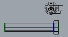
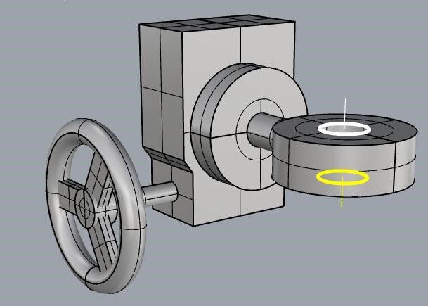
When a connection circle is green, it means it is not connected. While adding a piping element to your pipeline, the closest disconnected connection circle is highlighted in yellow, while the selected pipeline is highlighted in white. 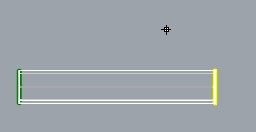 When two connection circles are connected, they become blue-colored. In the example below, the butterfly valve is connected to the pipe.
Options
RhinoPiping adds a tab in the rhino options where you can select:
- The nominal size display. Each connection circle has a nominal size and can be only connected with a piping element of the same nominal size. RhinoPiping handles two different display modes. One is named “DN”, it is the International standard notation in mm, and the other is named “NPS”, which is the Anglo-Saxon equivalent. (For example DN: 32 is equivalent to NPS: 1 ¼)

- The license information and activation. This part has been removed after RhinoPiping-1.0.9.

- The RP_Iso3D options, which are specific to the command RP_Iso3D

Layers
Every piping element created with RhinoPiping must be located in the layer named “Piping network”, or its sub-layers. If the piping layer “Piping network” does not exist, it will be created.
RhinoPiping protection
Some modifications of a pipeline created by RhinoPiping with a rhino3D command are forbidden to protect the piping data, for example:
- If you try to scale a piping element, you will get this message:

- If you try to delete/move/rotate (etc.) a piping element alone when its connection circles are connected, it will also be forbidden, and you will get this message:

These modifications would have been alright if the piping element hadn’t been connected (Try using the command “RP_Disconnect” if needed), or if your selection contains all the connected piping elements.
If you open a file with RhinoPiping elements with RhinoPiping uninstalled, it will work but you mustn’t modify any element belonging to the “Piping network” layer. (If you do, it can result in file corruptions, and make RhinoPiping crash later)
Additional attributes integration
 RhinoPiping is deeply integrated with a free rhino plugin named AdditionalAttribute. As its name suggests, AdditionalAttribute adds a special tab in rhino3D properties for attributes.
These attributes can be defined in RhinoPiping’s catalog (specific to a pipe class for example), calculated, read-only (or not), and a lot more. Special internal attributes will also be displayed, like the nominal diameter of the selected element, its type, and family, etc…

How To 's
How to add a Nominal Diameter in the allowed DN list
Every DN (Nominal Diameter) used in a piping class, an elbow class or a piping component must beforehand be declared in the file nominal-sizes.xml. If this rule is not followed, Rhinopiping won’t be able to start when launching Rhinoceros.
This file’s path is located in RhinoPiping “catalogs” folder. With windows 7, the default full path is: “C:\ProgramData\Navinn\catalogs\nominal-sizes.xml”
This file has two roles:
Limit the allowed DN to a predefined list Manage the equivalence between the DN (Nominal Diameter) and the NPS (Nominal Pipe Size – American standard) The values must absolutely be ascending. For example, to add the NPS 6 1/2, we must add it between NPS 6 and NPS 7:
How to add a piping component to your catalog
See RP_CC_CreateItem
How to create a pipe class
Every pipe class definition file are declared in the file pipe-classes.xml
This file is located in RhinoPiping’s “catalogs\pipe” folder. With windows 7-10 the default full path is: “C:\ProgramData\Navinn\catalogs\pipe\pipe-classes.xml”
In the example below, lines 3-4 are defining the existing attributes for the pipe classes. The “name” option is mandatory, the “type” option is not mandatory, and the “default” option is not mandatory but highly recommended, because when missing it may prevent the command AA_Report to run as it should.
Lines 6-7 are the respective paths of the secondary XML files where the pipe classes are defined. These files should be located in the same folder as for pipe-classes.xml. Using secondary XML files like this is only to help to get a clean structure, it does not correlate with the classes tree in RhinoPiping.
Now let say we need to add a copper piping class and register it in a new file named “Coper.xml”. We will declare it like this:
Then we will create a “Copper.xml” file in \Navinn\catalogs\pipe where the class will be registered. We could set every data in this file, but to make it easier, RhinoPiping lets you define the values in a CSV file, called from this XML. let see how it works:
Line 2 defines the category name for this class, and the units used for OD (outside diameters) and Thickness. Line 3 defines the class name and its tree position in RhinoPiping. In the example, the tree is set to: CopperClass / CustomClass / Class1. Line 4 lets us define the path for a .csv file where the values will be. With the option separator, it’s also possible to choose the separator for this file. The CSV is imported by columns in the same order as the attributes declared in the XML file. Lines 5 to 7 are mandatory internal attributes: DN (nominal diameter): The theoretical nominal diameter of the pipe. (Can be different with the real diameter). It is possible to use the NPS attribute instead. OD (Outside Diameter): The pipe’s real outside diameter thickness: The pipe’s real thickness.
The lines 8-9 are non-mandatory custom attributes declared in pipe-classes.xml
This is what the CSV file should look like if we want to only have a copper class with DN32 and DN40:
32;35;1.5;1.41 kg/m;Copper
40;42;2;1.61 kg/m;Copper
If we wish to add another copper piping class, we could just create a new CSV file and update the XML file like this:
Here is an example of the file “CopperClass2.csv”, with thicker pipes and the DN50 available:
32;35;2.5;1.41 kg/m;Copper
40;42;3;1.61 kg/m;Copper
50;53;3;1.8 kg/m;Copper
You can download this tutorial’s example here.
How to create a pipe class catalog attribute
For this tutorial, we assume you followed the previous one: “Creating a pipe class”
As for the pipe class file’s paths, the attributes dedicated to pipe classes are all declared in the file pipe-classes.xml
This file is located in Rhinopiping’s folder “catalogs\pipe”. With windows 7 the default full path is: “C:\ProgramData\Navinn\catalogs\pipe\pipe-classes.xml”
In the previous example, two attributes were already defined:
An attribute lineic-mass is typed to define a lineic mass. An attribute CATALOG:Material. The use of “:” is a way to define an attribute’s tree position. In RhinoPiping we will see an attribute Material under a group CATALOG.
To add an attribute Provider in the group CATALOG, we must add a line in the file:
Now if we restart Rhinoceros, in the attributes tab we will see our attributes as defined:
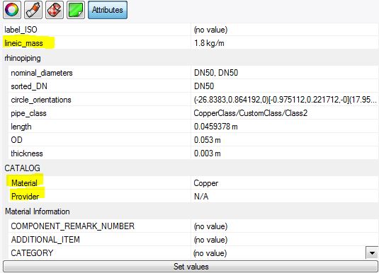 Nevertheless, our new attribute Provider always has its default value (here “N/A”), since we did not define its values for the different pipe classes.
To customize the providers for the two copper pipe classes we created in the previous tutorial, we must update the file “copper.xml” in \Navinn\catalogs\pipe , then add a column in the corresponding CSV files:
Nevertheless, our new attribute Provider always has its default value (here “N/A”), since we did not define its values for the different pipe classes.
To customize the providers for the two copper pipe classes we created in the previous tutorial, we must update the file “copper.xml” in \Navinn\catalogs\pipe , then add a column in the corresponding CSV files:
Our two classes CSV files will have to be modified accordingly:
32;35;1.5;1.41 kg/m;Copper;unimat
40;42;2;1.61 kg/m;Copper;unimat
32;35;2.5;1.41 kg/m;Copper;unimat
40;42;3;1.61 kg/m;Copper;unimat
50;53;3;1.8 kg/m;Copper;altitube
After restarting Rhinoceros, the attribute Provider now displays the appropriate values. You can download this tutorial example here.
How to create an elbow class
RhinoPiping can use two different kinds of elbows:
- The components owning the stereotype “elbow”.
They are created like any other components, so each of them has to be drawn and created manually, for each ND (Nominal Diameter) needed. This can be a bother, but gives us two interesting points:
- The component-type elbows are compatible with every pipe class from a software point of view. Once you created them, you can use them with any pipe classes. You will also be able to insert them with the “RP_AddComponent” command, as for any other end of line components.
- Since this kind of elbow is designed manually, it can have any form-factor and size. We can make it longer just on one side, or take into account the overlap needed if it is screwed on the pipe for example.
- The elbow classes. Less flexible, they have the huge advantage to be very fast to set up. In this tutorial, we will create two different elbow classes for the two pipe classes created in the previous tutorials.
Every elbow class is defined in only one file named elbow-classes.xml.
This file is located in RhinoPiping’s folder “catalogs\elbow”. With windows 7 the default full path is: “C:\ProgramData\Navinn\catalogs\elbow\elbow-classes.xml”
The elbow classes can be defined in two different ways: from a curvature factor, or from curvature values. An elbow class is only compatible with one pipe class but a pipe class can have several elbow classes.
Example of a curvature factor pipe class:
For each factor needed, we add a line with these properties:
- “key”: the elbow class name
- “factor”: The curvature factor (It will be multiplicated by the diameter)
- “pipe-class”: The associated pipe class name and tree path
Example of a tabulated curvature pipe class:
For each DN (Nominal diameter) used in each class, we define the curvature radius.
When updated, our elbow-classes.xml file should look like this:
Caution! To create an elbow component, it can be faster to create first an automatic elbow, then explode it in Rhino3D and make it a component.
You can download this tutorial’s example here.
How to create global attributes settings
How to change an object color to match an attribute value
It is possible to change quite easily some Rhino/RhinoPiping objects color to match a specific attribute. In our example, we with to have an attribute “Status”, with a choice between the value Built and the value Todo.
Creating the attribute
In default-attribute-spec.xml we must add:
Rhinoscript code
We will write the script as shown below, then run the command “ChangeColors” every time we want to update the colors.
How to create a template file for the command AA_Report
The template file is formated like a kind of .csv with a .tpl extension. It can be opened with a text editor like notepad.
When you create your template file, you must follow those rules:
- The separator must be ;
- If you are using a spreadsheet program like Excel for edition, check it won’t add double-quotes.
- Make sure all the attributes you are referring to have a default value. If they don’t, the command AA_Report will stop when meeting an attribute with no value. 1)
- A “cell” can contain text, attribute values, or both.
Example
Let’s build a typical example of a template file to generate a Bill of Materials. Create a text file and rename it for example “BillOfMaterials.tpl”. The template file will be read from top to bottom when `AA_Report` is running. So you may wish to begin with a simple line of texts for columns titles:
Label_ISO ;DN;Part number;Mass;Lineic mass;Material
The attributes values will be called like that: (example with label_ISO)
$(attribute:label_ISO)
We can look for different attributes for each kind of population. This is nearly always necessary since all piping elements don’t have the same attributes (for example only the elbows have a curvature attribute). To separate the population, we use filters. The most common way would be to separate pipes, elbows, and others:
$(filter:population:Pipe)$(attribute:label_ISO);;;;;
$(end-filter)
$(filter:population:Elbow)$(attribute:label_ISO);;;;;
$(end-filter)
$(filter:population:ComponentNode:)$(attribute:label_ISO);;;;;
$(end-filter)
As you can see, the line begins with the filter, and there is no separator before the first column definition. (We take the following line to end the filter.) The population:Elbow stands for the automatic elbows (not the components). If you leave nothing between two separators, it will leave a blank cell in the Bill Of Material. In the example above, `AA_Report` will create a CSV file with only the labels in the first column. Now we can complete it and add the line for column titles:
Label_ISO ;DN;Mass;Lineic mass;Material
$(filter:population:Pipe)$(attribute:label_ISO);$(attribute:rhinopiping:sorted_DN);$(attribute:CATALOG:Weight);$(attribute:lineic_mass);$(attribute:CATALOG:Material);
$(end-filter)
$(filter:population:Elbow)$(attribute:label_ISO);$(attribute:rhinopiping:sorted_DN);;;$(attribute:CATALOG:Material);
$(end-filter)
$(filter:population:ComponentNode:)$(attribute:label_ISO);$(attribute:rhinopiping:sorted_DN);$(attribute:CATALOG:Weight);;$(attribute:CATALOG:Material);
$(end-filter)
How to remove a component with the free LT edition
As you may have noticed, the command RP_RemoveComponent is not available for RhinoPiping LT free licenses. You can still remove a component with one more step:
- Disconnect the component with the command: RP_Disconnect
- Delete the component with the command: _Delete
- Re-draw the missing pipe portion with the command: RP_CreatePipeline
How to replace an elbow with the free LT edition
As you may have noticed, the command RP_ChangeElbows is not available for RhinoPiping LT free licenses. You can still remove a component with one more step:
- Disconnect the elbow with the command: RP_Disconnect
- Delete the component with the command: _Delete
- Re-draw the missing pipe portion with the command RP_CreatePipeline. While using the command select the new elbow class.
Commands (LT and Pro editions)
RP_CreatePipeline
 This one is RhinoPiping's most important command since it is the one with which you are going to draw your pipelines with.
Usage
- Run the command RP_CreatePipeline
- Pick the vertices of the polyline which will be pipeline's axis,
- Hit Enter (or right-click) to end the pipeline.
Snaps
If the Rhinoceros® snap “Point” is enabled, the command can:
- Extend an existing pipeline.
- Connect to an existing pipeline (these snaps are only defined after the second vertex picking)
- Start from tapping into an existing pipeline ( these snaps disappear after the first vertex is picked)
- End with tapping into an existing pipeline.
It may occur that RhinoPiping has difficulties connecting to an existing pipeline if too many snaps are enabled. Depending on the case, you may need to temporarily disable every snap except “Point”.
Pre-selection
If pipelines are pre-selected when the command starts, the snaps for connection or tapping are built only for the pre-selected elements.
Consistency
RhinoPiping always makes sure every piping element is compatible with the others in the same pipeline. When you change an option, it might change others. For example, if you switch from DN40 to DN50: if the current pipe class doesn’t have DN50, the pipe class should change automatically.
A pipeline can only contain one pipe class with compatible elbow classes. (You won’t be able to change the pipe class if you try to connect to an existing pipeline). The components are not associated with a specific pipe class. (You may use them with every pipe class).
Options
- Offset
When this option is enabled, the pipe will be drawn with an offset. Through the OffsetParam menu, you can choose its axis (X, Y, Z) and gap (Distance between the picked points and the pipe’s side).
- Angle
This option lets you define if the pipeline’s angles should be locked to a list of specific angles or free. AngleValues Let you register a list of allowed angles in degrees. This option is active only when Angle=Locked.
When using ortho mode, if you removed 90 from the parameter AngleValues, it may happen that no angle proposed by the component family satisfies the constraints induced by the ortho mode. In that case, Rhino Piping won't propose any elbow.
- Draw
This option configures the dynamic display of future pipeline during the vertices picking. You can choose between:
- Display axes (value Axes),
- Display pipes and elbows geometric forms (value PipesAndBents).
- Elbows
This option lets you change the elbows class of the pipeline. It can be changed after several vertices are picked.
When using ortho mode, if the elbows class is based on a component family, it may happen that no angle proposed by the component family satisfies the constraints induced by the ortho mode. In that case, Rhino Piping won't propose any elbow.
- Guide
If the value is Keep, the axis polyline of the pipeline is kept after the command. The default value is Destroy.
- Nominal Diameter
This option lets you choose the nominal diameter of the pipeline. This option is disabled when the pipeline starts with a continuation or a tapping.
- Pipes
This option lets you change the pipes class of the pipeline. The pipes class can still be changed after several vertices are picked. This option is disabled when the pipeline starts with a continuation or a tapping.
- Snap
This option lets you configure specific piping snaps. You can allow or forbid:
- Tappings
This option lets you change the tapping class of the pipeline.
RP_AddComponent

Presentation
This command adds a component to the model. The component can be inserted:
- At any position
- At a pipeline's end
- Into a pipe (if the component owns two coaxial connection circles).
The component is chosen among the catalog. The choice is limited to the components compatible with the context (selected pipeline…).
Usage
- Run the command RP_AddComponent
- Choose the pipeline into which you want to insert the component (right-click if you don't want to choose a pipeline)
- Choose the family of the component you want to insert
- If no pipeline has been chosen, choose which version you want to insert
- Click to insert the component.
Pre-selection
If a pipeline is selected before running the command, it will be used as command context (the step of the pipeline's choice is skipped).
Options
- ChangeComponent
This option allows changing the component to add. It is proposed when several components of the same family can be added. (For example when inserting tees)
Please note that the current component’s diameter(s) is displayed in the state bar.
- ShiftCircle
 Permutes the connection circles to choose which circle on the new component is connected to the end of the pipeline.
This option is not considered when inserting the component into a pipe.
- Swap
Permutes the connection circles to choose which circle is placed at the mouse cursor. This option applies when inserting a component into a pipe, not when connecting to the end of the line.
- TurnOver
This option turns the component over.
RP_Slide
 This command slides a component along its pipeline.
Usage
- Run the command RP_Slide
- Choose the component you want to slide
- Pick the new position.
Pre-selection
If a component is pre-selected, this component will be transformed.
Options
- Swap
Permutes the connection circles to choose which circle is placed at the mouse cursor. This option applies when inserting a component into a pipe, not when connecting to the end of the line.
RP_Connect
 This command connects two pipelines or two piping elements
Usage
- Run the command RP_Connect
- Choose the first end to connect,
- Choose the second end to connect.
- If the two connection circles were identical, they are just connected and become highlighted in blue. If not, then first selected will be moved with all its piping line, and then connected.
Pre-selection
Pre-selection is ignored.
Options
- ConnectAllMatchingCircles
When selected, Rhino Piping will check every circle on the active document, and connect them automatically if they are matching.
RP_Disconnect
 This command disconnects the selected piping element from its pipeline. The pre-selection is canceled if several piping elements were selected.
RP_Cut
 This command lets you cut a pipe. It becomes then two different pipes, with a green (disconnected) connection circle between them.


RP_Replace
 This command replaces a component with any other one compatible in shape and size.
If components are pre-selected, the command will replace, among these components, the ones of the chosen family. (RhinoPiping will then propose to select which family should be replaced)
This command replaces a component with any other one compatible in shape and size.
If components are pre-selected, the command will replace, among these components, the ones of the chosen family. (RhinoPiping will then propose to select which family should be replaced)
RP_Rotate
 This command rotates an element around the axis of one of its connection circles. It can also be used to rotate a larger part of a pipeline.
Usage
- Run the command RP_Rotate
- Choose the element to rotate (The highlighted circle defines the rotation's axis.)
- Pick a reference point or type the rotation's angle (The angle value must be expressed in degrees. If you type the angle value, the following step is skipped.)
- Pick reference point's new position.
- The rotation is applied to the element. If the new position of a previously connected circle is no longer compatible with the connection, the connection circle is disconnected.
Pre-selection
By default, you choose among all elements of the model. If elements are pre-selected, you choose among the selection.
Options
- RotateNeighbours
If the value is “True”, the transformation is also applied to the neighbors of the transformed element. This option is disabled if the neighbors cannot follow the transformation. (It's the case when the transformed element is on a loop.)
RP_TurnAround
 This command turns a component around an axis while keeping the connections. You just have to run the command, choose the component, and pick the symmetry’s axis.
RP_CC_CreateItem
Introduction
The creation of piping components for RhinoPiping is highly flexible and quite fast. You can create as many components as you want, even with the free RhinoPiping LT license. The main characteristics of a component will be:
- From one up to eight connection circles. Each of them can have a different diameter.
- No limitation concerning the shape. The component can contain curves, surfaces, solids, or meshes.
Preparing a Rhino3D model
Before it could be imported as a RhinoPiping component, you should add to your Rhino model a closed circle for each future pipe connection point. They will become the basis to generate the actual piping connection circle.
If your design allows it, the fastest way would be to use the Rhino command: _dupedge Else the command: _circle would obviously do the job

Tip for using an existing component as a basis:
- Insert the component with the command RP_AddComponent (don’t connect it to a pipeline)
- Use the command _explode: it won’t be anymore a piping component (No connection circles)
- Remodel it as needed, and then create a new component from it
Creating a component
- Select every element:
- Launch the command: RP_CC_CreateItem

- Name your component:
- The name shall not contain special characters and blank spaces, except “-” and/or “_”.
- Don’t use the diameter in the component’s name. All identical components with different diameters should have the same name because RhinoPiping will automatically use the right DN/NPS.
- The character “/” lets you define the hierarchy in the component tree.
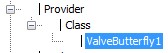
For example:Provider/Class/ValveButterfly1will appear later as:
- Select your connection circles. (If you followed this guide you created them before) For each of them, RhinoPiping will try to detect the corresponding nominal size and ask you for confirmation:
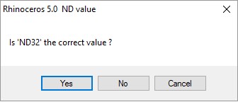
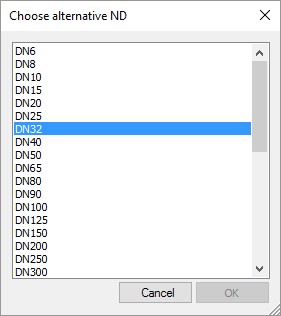
If you select no, you will be asked to choose the right nominal size:
- Check the connection circles’ orientation. Each of them should have an arrow pointed outward. Click near a circle to reverse its orientation.
- In some cases, the command will ask you if you want to confirm if you want to apply a stereotype (A special rule for this component).
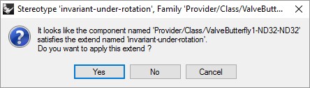
The most common stereotype is ‘invariant under rotation’. If you validate this one your component will ignore the rotation requests later. In most cases, you wouldn’t want that.
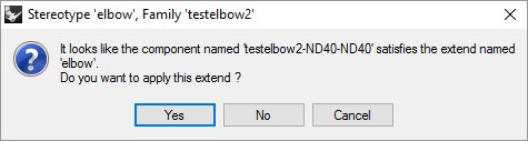
- Another stereotype is quite important; it is the ‘elbow’ stereotype. By allowing this one you will be able to use a component as an elbow.
RP_CC_CreateDressedItem (Rhinopiping PRO)
The dressed components are special piping components, made of several components each 5). The dressed component has its own attributes, but it is possible to “undress” it and make it back to the original components.
For example, you could group together a valve with its two flanges and joints, which would make it really faster to use when designing a pipeline.
The opposite command is available to decompose a dressed component as several base components: RP_ExplodeDressedComponent
Usage
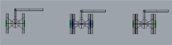 From left to right:
- The first one is a ball valve alone.
- The second one is a small portion of the line, including a ball valve, two joints, and two flanges. It is fine but it would be 5 components to insert every time.
- The last one is a dressed component, made from all the components aforementioned. It is a lot faster to insert in a pipeline (two clicks), and it avoids making a mistake while choosing the matching elements.
Commands (Pro edition only)
RP_ChangeElbows
 This command replaces an elbow (or several) with any other compatible elbow.
RP_ReplaceDiameters
 This command changes the diameter of a pipeline. Every piping element of the selected pipeline, including components, will be replaced. You will only be able to select compatible diameters. (For example, if a valve included in the selected pipeline only exists for DN40 and DN50, you will only be able to choose between these two sizes.)
RP_Stretch
 This command lets you stretch/shorten one pipe or several parallel pipes.
Usage
- Run the command RP_Stretch
- Choose the pipe to stretch
- (optionally) Choose other parallel pipes (In some cases (loop), this step is mandatory.)
- Pick a reference point
- Pick the new position of reference point, or type translation value
Options
- Roll
Switch the unchanged and transformed ends.
RP_Mirror
 This command creates the symmetry of a pipeline portion. The created components are the same as the original ones, only their position is symmetrical. The pre-selection is taken into account.
Usage
- Run the command RP_Mirror
- Select a pipeline or part of it (The completion option might help)
- Choose the mirror plane.
- Validate
Options
- Copy: This option is available only if you selected the whole pipeline. If you select yes, the original line is kept, else it is removed.
- Completion: This option helps with the selection:
- NoCompletion (Default): you will select components and pipes one by one CoaxialSection: you will select coaxial sections of your pipeline one by one
- SameDNsection: Your selection will be extended across the pipeline until there is a change of nominal diameter
- WholePipeline: The whole pipeline will be selected
- Mirror plane:
- Default: Select two points within the current CPlane
- 3points: Define a custom plane
- XAxis: Symmetry based on X axe
- YAxis: Symmetry based on Y axe
RP_Avoidance
 This command builds an avoidance on a pipe, in order to avoid an obstacle for example.


Usage
- Run the command RP_Avoidance
- Choose the pipe on which the avoidance is to be built. This step also determines avoidance's orientation: when the “Pick” option is not set to Middle, the first elbow will be on the same side as the closest connection circle of chosen point.
- Pick the first point on the pipe's axis. Depending on the “Pick” Option, it can be the Middle point or the first elbow position (vertex).
- Pick the end point.
Options
- Elbows
This option lets you change the elbow class of the pipeline. The elbows class can be changed after several vertices are picked.
When using ortho mode, if the elbows class is based on a component family, it may happen that no angle proposed by the component family satisfies the constraints induced by the ortho mode. In that case, Rhino Piping doesn’t propose any elbow.
- Angle
This option lets you define if the pipeline’s angles should be locked to a list of specific angles or free. AngleValues Let you register a list of allowed angles in degrees. This option is active only if Angle=Locked.
When using ortho mode, if you removed 90 from the parameter ‘AngleValues’, it may happen that no angle proposed by the component family satisfies the constraints induced by the ortho mode. In that case, Rhino Piping won't propose any elbow.
- Depth
This option lets you enter on the keyboard the avoidance's depth.
- Length
This option lets you enter on the keyboard the avoidance's length.
- Pick
This option lets you choose if the first selected point will be the centered vertex or the side vertex of the avoidance.
RP_RemoveComponent
 This command deletes a component and tries to redraw a pipeline instead. Just launch the command, select the component and validate to remove it. Pre-selection is taken into account.


An error will occur if the pipes connected to the removed components are not from the same pipe class. This is due to a limitation of the components: as their class is not checked, you may connect them with several non-compatible pipe classes. In this case, the RP_RemoveComponent command would try to connect two pipe classes that are not supposed to be compatible.
Commands for attributes
AA_Get Value
This command lets you read an attribute value for the selected rhino or RhinoPiping element (s), and display it in the command results. If the attribute path is left empty, every attribute will be read.
AA_SetValue
This command lets you set the value for a specific attribute. Several elements may be changed at once.
1)
Warning: Please remember that despite the attribute Label_ISO being created in the selected items when you run the command RP_Iso3D it is not included in the default attribute spec. Find the file `default-attribute-spec.xml` and add an entry point for the attribute Label_ISO with a default value to guarantee it will always have a value for the Bill of Materials. For example:
2)
connections at pipeline start or end
3)
at pipeline start or end
4)
double-tapping linking two pipes
5)
Available for RhinoPiping Pro only